Industrial 5G Router for In-Vehicle Applications
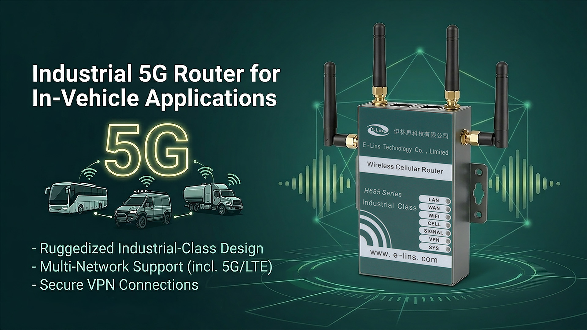
Industrial 5G Router for In-Vehicle Applications: How the H685f Handles Power, Vibration, and Always-On Connectivity
An in-vehicle router lives in a different world from a cabinet-mounted one. The power supply swings between 11 V and 32 V across the battery’s charge cycle and spikes far higher during engine start events. The chassis vibrates continuously at frequencies that fatigue connectors. The ignition cycles on and off dozens of times per day. A router that handles all of this reliably — while maintaining a VPN tunnel, managing three independent WAN paths, and fitting inside the electronics bay of a purpose-built vehicle — is a genuinely specialised piece of hardware. The H685f is designed for exactly that environment.
What Makes a 5G Router Genuinely Suitable for In-Vehicle Use?
An industrial 5G router for in-vehicle applications is not simply a compact router with cellular capability. Consumer-grade routers — and many routers marketed as “compact industrial” without specific vehicle qualifications — will eventually fail in a mobile platform, often within months of deployment. The reasons are consistent: the router was not designed for the power environment, the vibration profile, or the thermal cycling that vehicle operation imposes continuously and without accommodation.
The specific conditions that separate a vehicle-qualified router from one that merely fits inside a vehicle electronics bay are well-defined. First, vehicle power is not clean DC at a stable voltage — it varies across the battery charge cycle, spikes during motor start events, and drops during high-current loads. The ISO 7637-2 standard defines the transient voltage profiles that vehicle electronics must survive; hardware not rated to this standard may work on the bench and fail in the field after the first cold-start event. Second, vibration from road surfaces, engine mounts, and chassis resonance introduces cumulative mechanical stress on solder joints, connector seating, and PCB mounting hardware. Third, the ignition cycle creates repeated power-on/power-off events that stress both the router’s hardware and its software reconnection logic — a router that takes three minutes to re-establish its VPN after each engine restart creates a gap in connectivity that fleet operators experience directly.
The H685f addresses all three dimensions with hardware specifications drawn from the vehicle installation context rather than the cabinet context: ISO 7637-2 transient voltage protection, reverse polarity protection, ignition sensing with configurable time-delay shutdown, wide-voltage DC input covering the full range of vehicle power systems, and a vibration-rated alloy metal case. The compact 5G router for fleet telematics and vehicle IoT combines these vehicle-hardened hardware properties with 5G SA/NSA cellular, three-path WAN failover, and a housing measuring 100 × 60 × 21 mm — sized to fit where space is allocated, not designed around available space.
Key distinction: a router that survives vehicle installation is not the same as a router designed for it. Surviving requires tolerating the environment; being designed for it means the power system, protection circuitry, ignition logic, and mechanical construction were specified from the vehicle use case rather than adapted to it after the fact. The difference becomes visible after six months in service, not during bench testing.
Vehicle Installation Readiness Checklist
Before specifying a 5G router for a vehicle platform, confirm the following. Several of these items have no equivalent in a static cabinet deployment and are specific to the vehicle electrical and mechanical environment.
- What is the vehicle’s nominal system voltage — 12 V, 24 V, or 48 V — and what is the measured voltage range at the router’s planned tap point across full battery charge cycle and during engine cranking?
- Does the installation require ignition-sensing power management — automatic router power-on with ignition and delayed shutdown after engine off to complete data transfers before powering down?
- Is a fused inline connection required, and what fuse rating matches the router’s current draw at the vehicle system voltage? (The datasheet specifies 3 A for 9–24 V and 2.5 A for >24 V installations.)
- What are the vibration characteristics at the planned mounting location — direct chassis mount, suspended equipment rack, or engine compartment proximity?
- How many WAN paths will be available: cellular only, cellular plus in-cab Wi-Fi from a passenger network, or cellular plus Ethernet via a vehicle docking station?
- What cable routing path allows antenna cables to reach external mounting positions — roof, rear panel, or exterior surface — while avoiding pinch points, heat sources, and moving mechanical components?
- Does the vehicle’s RF environment create interference concerns — high-power radio equipment, inverters, or motor controllers in adjacent bays?
- What VPN architecture will be used for fleet connectivity, and has reconnection behaviour been tested across ignition cycling rather than just under stable power conditions?
Why the Vehicle Electrical Environment Demands More Than Standard Industrial Specs
The vehicle power environment is one of the harshest DC power environments in industrial electronics, and it is frequently underestimated by engineers who have specified routers for fixed cabinet installations without previous vehicle experience. A 12 V vehicle system does not deliver 12 V. It delivers somewhere between 11 V when the battery is partially discharged and the engine is off, and approximately 14.4 V when the alternator is charging. During engine cranking, voltage can momentarily drop to 6–8 V. During load dump events — when a large electrical load is suddenly disconnected — voltage can spike to 40 V or more in a poorly-suppressed circuit. In 24 V truck and commercial vehicle systems, these ranges scale proportionally.
The ISO 7637-2 standard defines the specific transient profiles — pulse shapes, durations, amplitudes — that vehicle electronics are expected to survive. Compliance with this standard is not a marketing claim; it is a tested specification. A router with ISO 7637-2 compliance has been validated against load dump pulses, crank interference, and the other transients that vehicle electrical systems generate in normal operation. One without this compliance may function normally for months — and then fail after a particularly aggressive engine cold-start on a winter morning when battery voltage dropped further during cranking than it did during the test phase.
In field support across fleet deployments on commercial trucks, emergency vehicles, and rail maintenance units over several years, we have observed that the majority of early in-service router failures — those occurring in the first three to six months rather than at end-of-life — trace to one of three causes: voltage transients exceeding the router’s protection threshold during high-demand cranking events, connector loosening from vibration at mounts that were not specified for the installation’s vibration frequency and amplitude, and VPN reconnection failures after ignition cycles where the router’s reconnection timeout was shorter than the cellular registration time on the vehicle’s carrier in that coverage zone. All three of these are design and specification failures, not random hardware failures — and all three are addressable at the specification stage rather than through field replacements.
Ignition Sensing: The Feature That Changes the Operator Experience
Ignition sensing — where the router monitors the vehicle’s ignition signal line, powers on automatically when the vehicle starts, and shuts down after a configurable delay when the engine is switched off — sounds like a convenience feature. In a fleet context, it is an operational necessity. Without it, the router must either be connected to a power source that remains live after ignition off (draining the battery during parking) or be connected to the ignition circuit and powered off immediately when the engine stops (losing data mid-transfer and requiring a full cold-start reconnection on next use).
The time-delay shutdown in ignition-sensing mode addresses the data-transfer completion problem: the router remains powered for a configured period after ignition off — long enough to complete any pending data uploads, flush buffers, and properly close VPN tunnels before powering down. On the next ignition event, it powers on cleanly and begins the cellular registration and VPN re-establishment process so that connectivity is available as quickly as possible during the vehicle’s pre-departure checklist. For a 5G router with ignition sensing for fleet vehicles, this behaviour is a specific hardware feature, not software configuration on a generic router — it requires a dedicated ignition input line and the hardware logic to implement the time-delay shutdown correctly.
An emergency services organisation deploying routers in a mixed fleet of ambulances and command vehicles came to us after experiencing repeated connectivity gaps during shift changes — the period when vehicles were returned to the depot, handed over to the next crew, and redeployed within 20–30 minutes. Their previous routers had no ignition sensing; they were wired to the vehicle’s permanent power supply to avoid battery drain, which meant they remained powered during the depot stop but accumulated missed VPN reconnections from brief power interruptions during vehicle wash cycles. The H685f’s ignition sensing, configured with a four-minute shutdown delay, resolved this: the router powered down cleanly at the end of each shift, allowed the vehicle’s electrical systems to be isolated completely during wash and maintenance, and powered back on with the next crew’s ignition event. Depot staff reported that the “can’t connect” complaints from crews at the start of shifts — previously occurring on roughly 15% of deployments — essentially stopped within the first month after the fleet upgrade.
Key Features for In-Vehicle 5G Router Selection
The feature set for a vehicle-mounted router is partly overlapping with cabinet-mounted industrial routers and partly distinct. The overlap covers VPN, management, and cellular configuration. The distinction covers power protection, mechanical design, ignition integration, and the three-path failover capability that matters specifically for vehicles moving through varying coverage environments.
1. ISO 7637-2 Transient Voltage Protection and Reverse Polarity Protection
ISO 7637-2 compliance confirms the router’s protection circuitry has been validated against the transient pulses generated by vehicle electrical systems: load dump, cranking interference, and switching transients from inductive loads. Reverse polarity protection ensures the router is not destroyed if the vehicle’s battery is reconnected with incorrect polarity during a battery change or jump-start — a situation that damages unprotected equipment irreversibly and costs more to replace than the battery that caused it. Both protections should be confirmed from the hardware specification rather than assumed from a general “industrial grade” claim.
2. Wide-Voltage DC Input — 5–40 V (5–60 V Option)
A 5–40 V DC input range covers 12 V vehicle systems with their full charging and transient range, 24 V commercial and heavy vehicle systems, and 48 V light electric vehicle architectures without an intermediate DC-DC converter. The 5–60 V option extends coverage to higher-voltage bus architectures found in some rail, marine, and specialist vehicle platforms. For an in-vehicle 5G router with wide-voltage input for 12V and 24V systems, this range eliminates the intermediate regulator that would otherwise be a component in the vehicle’s electrical modification, reducing installation complexity and removing a potential failure point from the wiring design.
3. Dual Power Inputs with Automatic Failover
Two independent power inputs allow the router to be connected to both the vehicle’s main power bus and a secondary source — an auxiliary battery, a UPS module, or a second circuit protected by a different fuse. If the primary supply is interrupted — by a blown fuse, a loose connection from vibration, or a momentary voltage excursion — the router transfers to the secondary supply without resetting the cellular link. For emergency vehicles, transit vehicles, and any platform where the consequence of connectivity loss during an event is significant, dual power input is a meaningful architectural choice rather than a redundancy-for-its-own-sake specification.
4. Three-Path WAN Failover: Cellular, Ethernet WAN, and Wi-Fi Client
A vehicle moving through a geographic area encounters varying cellular coverage — signal dropouts in tunnels, reduced signal in underground parking structures, and complete loss in specific geographic dead zones. The H685f’s three-path WAN failover manages cellular as the primary path, while Ethernet WAN (from a vehicle docking station, a depot Wi-Fi bridge, or a fixed connection during layover) and Wi-Fi client (connecting to a depot or roadside network) provide fallback paths. Load balancing across available paths allows bandwidth to be aggregated when multiple paths are simultaneously active — useful for passenger Wi-Fi on transit vehicles where both cellular and depot Ethernet may be available during boarding.
“The three-path failover is the feature most operators discover they needed after they thought they only needed one. They spec the router for cellular connectivity and then, six months later, someone asks why the vehicle doesn’t have better connectivity when it’s parked at the depot — where there’s a Wi-Fi network ten metres away. Adding Wi-Fi client as a failover path at commissioning costs nothing in hardware and closes the depot-connectivity gap completely. The operators who configure all three paths from day one don’t have that conversation.”
— E-Lins application engineering team5. Ignition Sensing with Configurable Time-Delay Shutdown
The router’s ignition input line connects to the vehicle’s ignition circuit. When the ignition is switched off, the router begins a configurable countdown — typically two to ten minutes — during which it completes pending operations before powering down. When the ignition is switched on, it powers up and begins cellular registration. This prevents battery drain during vehicle rest periods, protects data integrity during driver changeovers, and eliminates the manual power management that would otherwise require driver intervention to maintain connectivity reliably across shift boundaries.
6. Vibration and Shock Rated Alloy Metal Case
The H685f’s alloy metal case is rated for vibration and shock at the specification level — not simply described as “robust” in marketing copy. For mounting on vehicle chassis, equipment racks, or bracket systems subject to road-surface vibration and speed-bump impacts, this rating provides the basis for specifying the mounting hardware and isolation design appropriate to the installation. The 100 × 60 × 21 mm footprint and 230 g weight (without antennas) are also relevant here: smaller mass means less inertial force at a given vibration amplitude, reducing the mechanical stress on mounting points compared to a larger, heavier device.
7. GPS/Beidou with External SMA Antenna Connector
GPS/Beidou positioning is an optional feature on the H685f that extends its role from connectivity device to positioning device — relevant for fleet tracking, geofenced operation policies (automatic feature restriction outside defined geographic zones), driver behaviour analytics, and asset recovery. The external SMA antenna connector allows the GPS antenna to be positioned on the vehicle’s roof or exterior where sky visibility is unobstructed, rather than relying on internal antenna placement inside a shielded vehicle body.
8. RS232/RS485 for Onboard Equipment Integration
Many vehicle onboard systems — tachographs, driver information terminals, fare collection systems, temperature monitoring units in refrigerated transport, and legacy diagnostic interfaces — communicate over RS232 or RS485 rather than Ethernet. The H685f’s serial port allows these systems to send data over the cellular connection without a separate serial-to-IP converter in the vehicle’s electronics rack, reducing component count in an environment where every installation item requires its own mounting, wiring, and maintenance consideration.
E-Lins H685f: Industrial 5G Router for In-Vehicle and Mission-Critical IoT
The E-Lins H685f is the baseline industrial 5G router in E-Lins’ H685 series — the variant combining PoE In, RS232 serial, 4× DI/DO, and EN 18031 compliance in the super-mini 100 × 60 × 21 mm alloy housing. Its vehicle-specific protections — ISO 7637-2 transient voltage compliance, reverse polarity protection, ignition sensing, and wide-voltage input — are integrated into the hardware design rather than added as external accessories.
E-Lins H685f Industrial 5G IoT Router with PoE In, RS232 and DI/DO
Super-mini industrial 5G SA/NSA router with ISO 7637-2 transient protection, reverse polarity protection, ignition sensing, 5–40 V DC wide-voltage input, dual power failover, RS232/RS485, 4× DI/DO, PoE In, GPS/Beidou option, three-path WAN failover, and full VPN suite. EN 18031 compliant. OEM/ODM supported.
The Specification Details That Matter Most for Vehicle Integration
The H685f’s size — 100 × 60 × 21 mm, 230 g without antennas — is a legitimate integration advantage rather than a marketing description. In a vehicle electronics bay shared with communication equipment, a DVR, a driver terminal, and its associated wiring, the difference between a 100 mm and a 200 mm router footprint is not abstract; it determines whether the device fits in the planned space or requires a bracket modification and the associated time and cost. The 21 mm height in particular allows the H685f to fit in enclosures designed for DIN-rail equipment where the available depth is constrained by the enclosure door clearance.
The storage temperature rating of −40 °C to +85 °C is relevant for vehicle fleets that are parked outdoors in winter climates — a router stored at −40 °C in a parked vehicle overnight must be able to start up reliably when the engine and ignition come on the next morning, without requiring a pre-warming period or generating startup errors from cold-soak effects on capacitors and other temperature-sensitive components.
The DI/DO ports’ SMS and email alert capability is specifically useful in vehicle applications for generating automatic notifications on hardware events — ignition status changes, door open/close, equipment status signals, or emergency button presses — without requiring an intermediate controller to manage the alert logic. For a small fleet operation or a lone-worker vehicle deployment, this effectively gives the H685f the capability to send a “vehicle started,” “door opened,” or “emergency activated” message to a monitoring system directly from the hardware signal, without application software running on a separate device in the cab.

E-Lins H685f — 100×60×21 mm industrial 5G router with ISO 7637-2 protection, ignition sensing, dual power failover, and RS232/DI/DO for in-vehicle and mission-critical IoT deployment
Which Vehicle Application Suits the H685f?
The H685f’s vehicle-specific hardware protections make it appropriate across a range of mobile platforms. The specific configuration — particularly GPS, Wi-Fi generation, and serial interface — should be matched to what each vehicle type actually needs rather than specified to the maximum across the board.
Emergency Services Vehicles
- Ignition sensing for clean shift-change power management.
- Three-path failover maintains connectivity through coverage gaps.
- DI/DO for emergency button, bay door sensor, and equipment status.
- VPN secures data link to control room and CAD systems.
- Wide-temp range covers overnight outdoor parking in cold climates.
Public Transit and Passenger Vehicles
- Wi-Fi AP provides secure passenger connectivity on one radio.
- 5G cellular handles CCTV upload and telemetry on the other.
- RS232 integrates fare system, passenger counting, or info display.
- Depot Ethernet WAN via docking station for batch data sync.
- NMS manages large bus/rail fleet from a central platform.
Commercial Freight and Logistics
- GPS/Beidou enables real-time fleet tracking.
- RS232 integrates tachograph or temperature monitoring unit.
- 24 V truck power system covered by wide-voltage input.
- DI/DO monitors refrigeration unit alarms and door seals.
- VPN secures proof-of-delivery and load data to TMS platform.
Rail and Specialist Vehicles
- Wide-voltage option (5–60 V) for higher-voltage rail DC systems.
- ISO 7637-2 protection handles traction system transients.
- Super-mini size fits constrained rolling stock equipment racks.
- OSPF/BGP routing for integration with wayside network nodes.
- SNMP v3 for integration with existing railway NMS platforms.
Comparison: Vehicle-Qualified vs Standard Industrial Router in a Vehicle
The table below illustrates the specific differences between a router designed for vehicle installation and a standard industrial router used in vehicle applications without vehicle-specific qualifications.
| Specification | H685f (vehicle-qualified) | Standard industrial router (no vehicle spec) |
|---|---|---|
| Transient protection | ISO 7637-2 validated, built-in | General industrial protection; vehicle transients may exceed rating |
| Reverse polarity | Protected by hardware design | Often absent; battery reconnection error can destroy unit |
| Ignition sensing | Dedicated ignition input, configurable delay | Not available; requires external power management |
| Voltage input range | 5–40 V DC (60 V option) | Often 9–36 V or 12–48 V; may not cover full vehicle range |
| Dual power failover | Standard feature | Sometimes available, often optional |
| Storage temperature | −40 °C to +85 °C | Typically −20 °C to +70 °C; cold-soak startup risk |
| Vibration rating | Vibration and shock rated alloy case | Typically rated for fixed panel; mobile vibration profile untested |
| WAN paths | Cellular + Ethernet WAN + Wi-Fi client | Varies; often cellular + Ethernet WAN only |
| Expected failure mode | Gradual performance degradation at end of rated lifespan | Early failure from voltage transient, cold-start, or vibration fatigue |
Common Mistakes When Installing 5G Routers in Vehicles
Using a Standard Industrial Router Without Vehicle Power Protection
The most common and most costly mistake is selecting a router rated for fixed cabinet installation and deploying it in a vehicle, based on the logic that “industrial grade” should be sufficient. Standard industrial routers are typically validated for stable DC power within a defined range — they are not validated against ISO 7637-2 transient profiles. The first cold-start voltage dip or load-dump transient above their protection threshold can cause permanent failure. This failure is invisible in bench testing, appears unpredictably in field service, and produces failures that are attributed to “bad batches” or “unknown causes” rather than identified as a specification mismatch.
Wiring Without an Inline Fuse Appropriate to the Installation Voltage
The H685f datasheet specifies the required fuse ratings clearly: 3 A for 9–24 V installations, 2.5 A for installations above 24 V. These ratings protect the router’s input wiring from overcurrent in fault conditions. Installing without a fuse, or with an oversized fuse carried over from a previous installation, removes the protection that prevents a wiring fault from becoming a fire risk. Fuse rating should be confirmed against the operating voltage, not reused from a previous router installation without checking the specification.
Routing Antenna Cables Near Engine Heat Sources or Moving Components
Antenna cables routed near exhaust systems, engine manifolds, or through bulkhead locations adjacent to high-temperature components will degrade over time — the insulation softens, the cable jacket cracks, and signal quality deteriorates in ways that are difficult to diagnose as a cable problem rather than a coverage problem. Similarly, antenna cables passing through door seals, over hinge mechanisms, or near moving machinery will fatigue from repeated flexing. All antenna cable routing should be finalised at installation with heat sleeve protection near any heat source and proper strain relief at all flexing points.
Testing VPN Reconnection Only Under Stable Power, Not Across Ignition Cycles
A VPN tunnel that re-establishes correctly after a manual router reboot on the bench may not behave identically after an ignition power cycle in the field, where the cellular registration sequence, the network attach time, and the VPN handshake sequence all depend on conditions that differ from a controlled reboot. Testing VPN reconnection specifically across ignition cycles — power off, wait, power on, measure time to tunnel establishment — should be part of commissioning for every vehicle deployment, not assumed to be covered by bench-based VPN configuration testing.
Positioning the Router Inside a Metal Equipment Box Without Planning Antenna Cable Routes
A router placed inside a sealed metal equipment enclosure for physical protection will have its cellular antenna signal attenuated by the enclosure walls, as discussed in earlier articles in this series. In a vehicle, this is even more significant because the vehicle body itself adds a second layer of shielding around the equipment box. Antenna cables must exit the enclosure and the vehicle body to reach external antenna mounting positions — roof, rear panel, or exterior bracket — for signal quality to be maintained. This cable routing path should be planned before the enclosure is mounted, not discovered as a problem when the installation is otherwise complete.
Application Scenarios for In-Vehicle 5G Routers
The H685f’s combination of vehicle-specific hardware protections, 5G cellular, three-path failover, serial interface, and GPS makes it relevant across a range of mobile platforms where connectivity is operationally critical rather than a convenience.

Ambulance and Emergency Services
5G connectivity for patient data transmission, CAD integration, body-worn camera uploads, and crew communications. Ignition sensing manages power across shift changes without manual intervention.

Public Transit Buses and Trams
Passenger Wi-Fi on one radio, CCTV and telemetry on 5G, fare system integration over RS232, and depot batch sync over Ethernet docking — all managed from a single router that fits behind the driver’s equipment panel.

Commercial Freight and Logistics
GPS fleet tracking, tachograph data transmission, refrigeration monitoring via DI/DO, and driver tablet connectivity over 5G. The 24 V truck power system is covered directly by the H685f’s wide-voltage input.

Rail and Rolling Stock
Passenger information, CCTV, condition monitoring, and wayside network handoff on rolling stock. The wide-voltage option covers rail DC bus architectures, and OSPF routing integrates with trackside network nodes.

Law Enforcement and Command Vehicles
Secure VPN connectivity to force management systems, ANPR camera data upload, body-worn camera sync, and mobile command functionality — all on a router whose 100×60×21 mm footprint leaves room in the equipment console for other hardware.

Construction Plant and Off-Highway Equipment
Excavators, cranes, and utility vehicles use the H685f for remote diagnostics, GPS tracking, hours monitoring, and telematics over 5G. The ISO 7637-2 protection and wide-temperature range handle the harsh electrical and thermal environment of heavy plant.
Extended Reading
E-Lins H685f Product Page — Full specification, band table, ordering information, and variant options for the industrial 5G IoT router.
IoT 5G Router Category — Browse the full E-Lins 5G router range across compact, standard, and feature-rich configurations.
H685f Wi-Fi 6 Variant — The Wi-Fi 6 / 802.11ax configuration of the H685f for AGV and high-density wireless environments.
H900f Dual SIM 5G Router — For vehicle installations requiring dual SIM carrier redundancy and Active PoE Out to onboard cameras.
GSMA 5G IoT Overview — Industry background on 5G IoT use cases including smart transportation and connected vehicles.
Project Inquiry — Share your vehicle type, power system voltage, serial equipment list, coverage region, and fleet size for a tailored recommendation.
FAQ
What does ISO 7637-2 compliance actually mean for a vehicle router?
ISO 7637-2 is an automotive standard that defines specific electrical transient pulses — generated by vehicle systems during normal operation — that vehicle electronics must survive. These include load dump pulses (when a large electrical load is suddenly disconnected from a running alternator), cranking interference (voltage dips and oscillations during engine start), and switching transients from inductive loads like motors and solenoids. Compliance means the router’s protection circuitry has been validated against these pulse profiles to specific amplitude and duration requirements, not just that it has general over-voltage protection of unspecified threshold. For vehicle installation, it is the difference between protection that was designed for the actual environment and protection that may or may not cover what the environment actually delivers.
How does ignition sensing work and how is it configured?
The H685f’s ignition input connects to the vehicle’s ignition circuit — the same signal line that powers other vehicle electronics during run mode. When the ignition is switched off, the router starts a configurable countdown timer rather than powering down immediately. During this delay, it completes pending data transfers, flushes buffers, and properly terminates VPN tunnels before powering down. When the ignition is switched on, it powers up and begins cellular registration. The delay duration is configurable through the router’s management interface and should be set to cover the typical data-transfer completion time for the specific application — longer for vehicles that upload large video files at end of shift, shorter for light telemetry applications.
What fuse is required for the H685f in a vehicle installation?
The H685f datasheet specifies an inline fuse for vehicle installations: 3 A for 9–24 V systems and 2.5 A for systems above 24 V. This fuse should be installed as close to the power source tap as practical to protect the wiring run between the tap and the router. Using an incorrectly sized fuse — either too small (nuisance trips) or too large (inadequate protection) — is a common installation error. The fuse rating is specified for the router’s power draw at the installation voltage; it should not be upsized to avoid blown-fuse interruptions, as the blown fuse may be indicating a legitimate fault condition.
Can the H685f operate on both 12 V and 24 V vehicle systems without modification?
Yes. The 5–40 V DC input range covers both 12 V and 24 V nominal vehicle systems across their full operational voltage range — from low battery at approximately 11 V to fully-charged alternator output at approximately 28–29 V for 24 V systems — without any hardware modification or external voltage regulation. The 5–60 V option extends this to higher-voltage architectures. The fuse rating should be rechecked when moving between vehicle system voltages, as the appropriate rating differs between 12 V and 24 V installations.
How does three-path WAN failover work in a moving vehicle?
The H685f monitors all three available WAN paths — cellular, Ethernet WAN, and Wi-Fi client — continuously. Cellular is typically the primary path for a vehicle in motion. Ethernet WAN via a docking station or fixed connection becomes available when the vehicle is at a depot or rest point. Wi-Fi client can connect to roadside hotspots, depot networks, or vehicle-to-vehicle networks when available. When the primary path drops — a cellular coverage gap, a tunnel, a brief signal loss — the router automatically routes traffic through the next available path. When the primary path recovers, it can failback automatically. Load balancing can aggregate bandwidth across simultaneously available paths — combining cellular and depot Wi-Fi for maximum throughput during a layover, for example.
What is the difference between the H685f and the H685f Wi-Fi 6 variant for vehicle use?
The base H685f and the Wi-Fi 6 (802.11ax) variant share the same vehicle-specific hardware protections, power input, ignition sensing, serial interface, and DI/DO. The difference is the Wi-Fi radio generation. The base variant uses 802.11a/b/g/n/ac (Wi-Fi 5), which is appropriate for most vehicle applications involving a small number of onboard client devices. The Wi-Fi 6 variant is relevant when the vehicle serves many simultaneous Wi-Fi clients — passenger vehicles with tens of concurrent users, or AGV platforms operating in dense wireless environments where Wi-Fi 6’s OFDMA capability maintains lower latency as device count rises. For a logistics vehicle with one or two driver devices, the Wi-Fi 5 variant is the more cost-appropriate choice.
Can the DI/DO ports send automatic alerts from vehicle hardware events?
Yes. The H685f’s four DI/DO ports support SMS and email alerts based on digital input state changes. A door open sensor, an emergency button, an ignition line, or a refrigeration unit alarm can trigger an automatic SMS or email notification when its state changes, without requiring a separate IoT gateway or application server to manage the alert logic. DO ports can also be used for output actions — activating a relay, enabling a peripheral, or signalling a status indicator — triggered by remote command or local logic conditions configured in the router.
How does GPS/Beidou integration work on the H685f?
GPS/Beidou is an optional factory-fitted feature with an external SMA antenna connector. When fitted, the router’s GNSS receiver generates position, speed, heading, and timestamp data that can be forwarded to a fleet management platform via the cellular connection, logged locally, or used in geofencing policy decisions. The external SMA connector is important for vehicle installation: the antenna must be mounted on the vehicle’s roof or exterior surface with unobstructed sky visibility, which is achieved by routing an SMA cable from the router’s antenna port to the external antenna position — exactly the same approach used for the cellular antennas.
What serial protocols does the RS232/RS485 port support for vehicle equipment integration?
The H685f’s serial port supports transparent serial-to-IP tunnelling compatible with RS232 and RS485 physical layers, covering Modbus RTU, tachograph communication protocols (including some implementations of the digital tachograph interface), proprietary manufacturer protocols from vehicle equipment vendors, and any application communicating over standard serial physical layers. Protocol translation to application-layer formats (Modbus TCP, MQTT, HTTP) may require middleware or configuration at the receiving server depending on the target platform. The datasheet also notes Modbus is explicitly supported, covering the most common industrial serial protocol used in vehicle monitoring and control applications.
Does the H685f support the SNMP monitoring needed for integration with fleet management NOC tools?
Yes. The H685f supports SNMP v1, v2c, and v3 — including v3’s authentication and encryption capabilities, which are relevant for fleet management environments where the management traffic itself needs to be secured. SNMP integration allows the H685f to be monitored through standard NOC tools alongside other network infrastructure, reporting signal strength, WAN path status, VPN tunnel health, data usage, and device uptime without requiring E-Lins’ own NMS platform to be the sole management interface. The NMS platform remains available as an option for fleet-scale configuration deployment and firmware management.
Conclusion: The Vehicle Environment Demands More Than “Industrial Grade” — It Demands Vehicle Grade
The case for an industrial 5G router for in-vehicle applications built around vehicle-specific hardware protections is not a nuanced one — it is a direct consequence of what vehicle electrical systems actually do, compared to what general industrial specifications assume. ISO 7637-2 transient protection, reverse polarity protection, and ignition sensing are not premium features; they are the minimum specification for a device that will reliably survive vehicle electrical environments across a multi-year service life. Routers without them may work — until the cold start that delivers a transient the hardware was not designed to absorb, or the battery reconnection after a flat, or the load dump from a faulty alternator.
The H685f’s combination of these vehicle-specific protections with 5G SA/NSA cellular, three-path WAN failover, RS232 serial for onboard equipment integration, four DI/DO ports with SMS alerting, optional GPS/Beidou, and a 100 × 60 × 21 mm footprint addresses the in-vehicle connectivity requirement as a complete specification rather than as a general-purpose router adapted to a specialised environment.
Before finalising an in-vehicle router specification, confirm the following:
- Measure the actual voltage range at the planned tap point across the full battery cycle and engine cranking event — do not rely on the vehicle’s nominal system voltage as a proxy for the real range the router must handle.
- Configure and test all three WAN failover paths during commissioning — cellular, Ethernet WAN, and Wi-Fi client — rather than leaving non-cellular paths unconfigured for “future use.”
- Test VPN reconnection specifically across ignition cycles with the real deployment SIM on the real carrier in the real coverage area, before the vehicle enters service.
Specifying Connectivity for a Vehicle Fleet or Mobile Platform?
Tell E-Lins your vehicle type, electrical system voltage, serial equipment list, coverage region, and fleet size. We will confirm whether the H685f covers your specific vehicle application or recommend the right configuration.
Contact Us